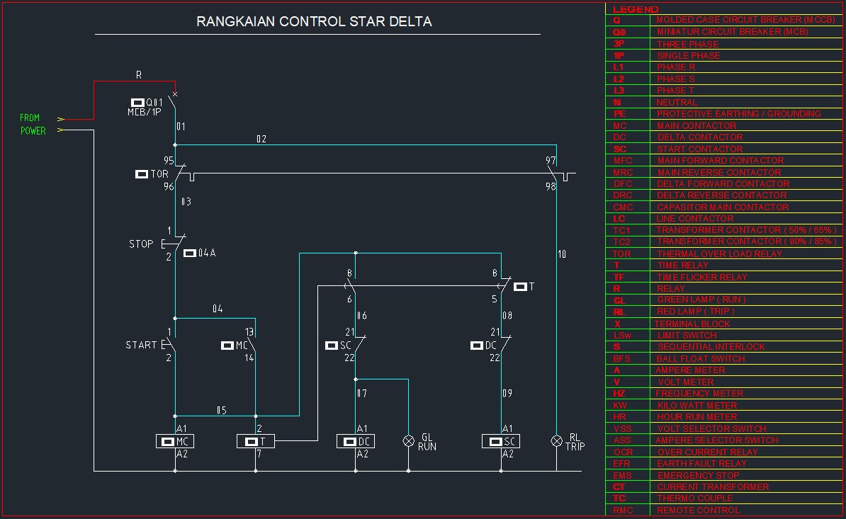
Star Delta Motor is an electric motor circuit consisting of a star and delta circuit used to reduce current jolts when the motor is switched on.
As seen in the diagram above, the Star Delta circuit consists of two motor circuits that work alternately: with star going first and then switching to the delta circuit. When a motor is just switched on, it will start with the Star circuit first, once the speed reaches 80%, the circuit will then switch to Delta.
The purpose of this is to avoid current jolts when starting the motor. Another purpose of the Star Delta circuit is so that the torque does not decrease. One of the advantages of the Star circuit is that the motor torque can be very high upon switching on.

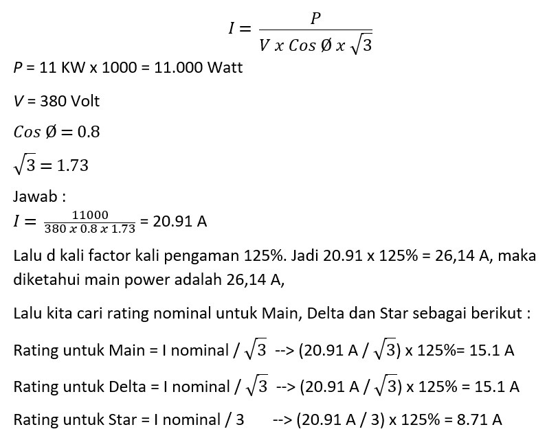
The diagram above is a power star delta circuit with a starter motor of 5.5 kW, 7.5 kW and 11 kW. From the diagram above with the known motor capacity, we can decide the power cable size to be used in the star delta circuit. Say, we take the capacity of 11 kW as an example, what will be the cable size of group A, B and C?
First, find out the motor ampere from the motor’s capacity of 11 kW

Cable Group A uses a cable size of minimum 4 mm2.
Cable Group B uses a cable size of minimum 2.5 mm2.
Cable Group C uses a cable size of minimum 1.5 mm2.
Or more than the cable size has been calculated above, or 1 step above the standard cable. With the phase cable color scheme R (red), S (yellow), T (black), and N (blue).

For control star delta, cables with a minimum size of 0.75 mm2 or above it may be used with an undecided phase cable color and a blue neutral cable.
That concludes our discussion on how to pick the right cable size for motor star delta.
Other Interesting Information:
1. Transmitting Power Sources From PLN To Your Home
2. Reviewing Grounding Cables and The Color Codes Used
3. Cable Usage Application for Submersible Pump
4. Understanding the Difference Between Medium Voltage and Low Voltage
5. 5 Techniques for Connecting Electrical Cables are Good and Correct